Navigation for Radio navigation

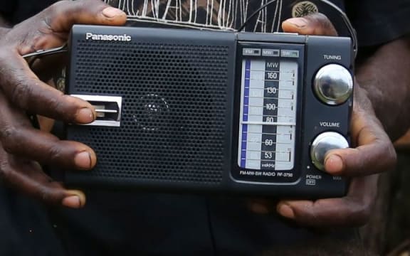
RNZ Pacific (formerly RNZI) provides comprehensive Pacific coverage with the very latest Pacific stories and an extensive online news archive. Podcasts, a live audio feed and on-demand programmes are also available.

Navigation for Station navigation
Pacific Waves: News In Depth
-
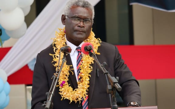
Queen's Gambit - Manasseh Sogavare re-elected in Solomon Islands
5 minutes agoThe incumbent prime minister has been re-elected in the East Choiseul constituency, opening move in the political chess match to form the next government of Solomon Islands.
-
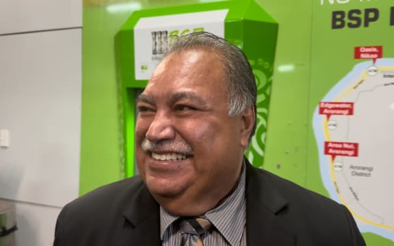
Baron Waqa negotiating - No start date for incoming PIF boss yet
The incoming head of the Pacific region's main political body is yet to sign his contract, almost six months after the 2023 Pacific Islands Forum Leaders meeting in Rarotonga.
-
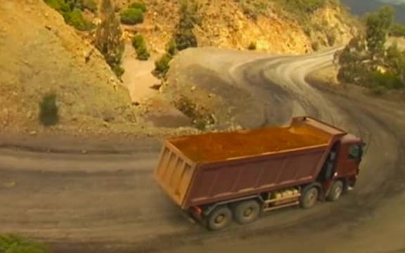
New Caledonia's nickel French 'pact' in limbo
The French-proposed "pact" to salvage New Caledonia's beleaguered nickel industry is still in limbo as the local Congress has decided to re-examine the whole document through a "special committee".
-
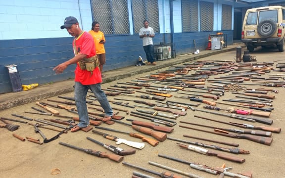
Bougainville guns: Concerns stolen firearms continue being used for illegal activities
Hundreds of high-powered firearms - allegedly stolen from weapons disposal sites - are still in use today, the police chief in the autonomous Papua New Guinea region of Bougainville says.
-
Pacific news in brief for April 19
A round-up of news in brief from around the region, including Papua New Guinea's public sector workfroce beholden to loan sharks.
-
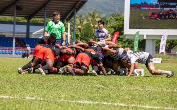
Pasifika Sipoti wrap
A wrap of sport that took place this week from around the region, including rugby, rugby league, soccer, tennis, swimming.

Browse By Country/Territory
Featured stories
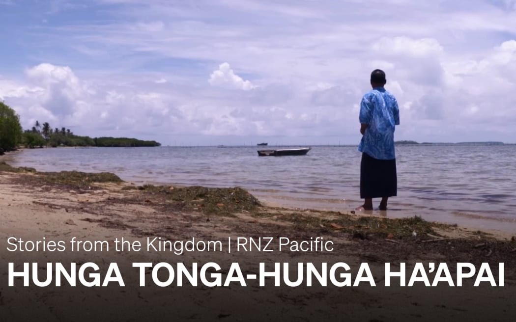
Documentary: Stories of Hunga Tonga-Hunga Ha'apai
January 15th marks two years since the eruption of the Hunga Tonga-Hunga Ha'apai volcano which devastated the kingdom of Tonga.
-
Here are the Pacific recipients of the New Year Honours list for 2024
4 Jan 2024Pasifika academics, artists, and advocates are among the recipients of New Zealand's 2024 New Year Honours.
-
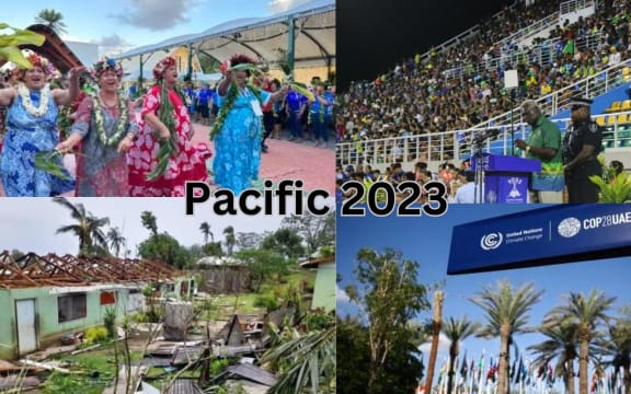
The year that was - RNZ Pacific looks back at the big issues of 2023
1 Jan 2024RNZ Pacific has covered stories on a diverse range of topics in 2023.
-
2023 replay: a look back at Pacific sport this year
1 Jan 2024Analysis - the 2023 sports season brought up surprises, disappointments, and a notable event in Honiara for the Pacific.
-
RNZ Pacific cyclone watch service is operating
18 Dec 2023RNZ Pacific has updated the on-air frequencies for its cyclone watch service for the 2023-2024 cyclone season.
-
RNZ marks 75 years of broadcasting shortwave into the Pacific
13 Nov 2023It has been 75 years since Radio New Zealand commenced broadcasting on shortwave frequencies, into the Pacific region.
-
Pacific Games: How it all began 60 years ago
12 Sep 2023It all began with a toss of a ball and the smash of a tennis racquet. The Cook Islands' Nono Tani's swift serve to her opponent at 9am on Thursday, August 29, 1963 thus kicked off the South Pacific Games in Suva. Video
-
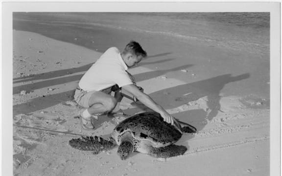
Marshall Islands sea turtle found to have nuclear contamination
28 Aug 2023Scientists studying tortoise and turtle shells near the Marshall Islands have found they contain nuclear contamination, according to an article in the journal PNAS Nexus.


Presenters
-
Christina Persico
Station: Pacific
-
Don Wiseman
Station: Pacific
Programme: World & Pacific News
-
Finau Fonua
Station: Pacific
Programme: World & Pacific News
-
Koroi Hawkins
Station: Pacific
Programme: Untold Pacific History
-
Lydia Lewis
Station: Pacific
Programme: World & Pacific News
-
Marama T-Pole
Stations: Pacific
Programme: News


Programmes
-
World & Pacific News
A bulletin of Pacific News and a sports report.
-
Tagata o te Moana
A weekly Pacific magazine programme features New Zealand and regional Pacific news, issues, information and music. This programme is also simulcast domestically on RNZ National.
-
News in Pacific Languages
Pacific language news bulletins in Tongan, Samoan, Pidgin, French, Cook Islands Maori and Niuean.
-
Pacific Waves
A daily current affairs programme that delves deeper into the major stories of the week, through a Pacific lens, and shines a light on issues affecting Pacific people wherever they are in…